MW Pulses and Spin Dynamics
In this section we first introduce the concepts of macroscopic magnetization and the rotating frame to describe the effects of MW pulses on a given spin system.
- The macroscopic magnetization M of a sample is obtained by adding up the contribution of all magnetic moments in a given sample volume. The precession of the magnetic moments about the external magnetic field B0 (taken along the z-axis) being out-of-phase in the absence of an external perturbation, the magnetic xy components are randomly distributed and a net magnetization (Mz) is observed only along B0 in the Boltzmann equilibrium.
- In the rotating frame the coordinate system rotates with the frequency νMW of the MW excitation about the z-axis. In this frame the excitation becomes time-independent and the resonances frequency for the electron spins is given by the offset Ω = ν-νMW of the true resonance frequency ν, obtained from the resonance condition in Eq. (3), from the excitation frequency νMW. The large static field B0 thus appears to be considerably reduced or even zero for the on-resonant case (ν = νMW).
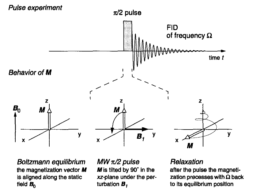
It is the interaction of M with the applied electromagnetic fields and the detector which gives observable pulse EPR spectra. In Fig. 9 the most simple pulse experiment, a single π/2 pulse, and the behavior of the magnetization under this pulse in the rotating frame are illustrated. The application of a MW pulse of frequency νMW perpendicular to the static field B0 leads to a nutation of M about the resultant of the static and the perturbing magnetic field during the pulse. Under the influence of a strong MW π/2 pulse applied along the y axis, the magnetization M is rotated to the x-axis5. This is shown for the on-resonant case in Fig. 9, where the z-component of the resulting field is zero. After the MW pulse is switched off, the magnetization vector relaxes back to its equilibrium position along z, thereby precessing with the offset frequency Ω. The precession leads to oscillating components Mx and My of the magnetization vector in the xy-plane which can be recorded as free induction decay (FID) after the MW pulse.
5 The flip angle of a MW pulse (e.g. 90° for a π/2 pulse) depends on its length tp and its amplitude. The axis about which the magnetization vector is rotated is given by the phase of the pulse.